 8ch DMX dimmer pack
Link Articolo Originale: http://www.hoelscher-hi.de/hendrik/english/dimmer.htm
This single phase diy dimmer pack was designed for small size and maximum stability. Though it is quite cheap because of its few parts, it has a firing table for power linearization and a 'switch mode' option for each channel integrated. An internal heat control prevents failures in the power units.
A dimmer pack consists of:
1 DMX-Transceiver
1 zc detection
1-8 power units
DMX-Transceiver (Rev. 3.01)
 With this modul DMX data can be received or transmitted.
Because of the complete usage of the RS485 converter, a bidirectional transfer of data is possible (i.e: RDM as described in ANSI E1.20). Till now this feature is only supported by a few expensive devices.
Though the circuit is only made of an AVR and few other parts I recommend a diy etched board.
 parts
parts
| IC1 IC2 IC3 B1 LED1 LED2 R1 R2,3,4 C1,2 C7 C5,6 SW1 Q1 connectors |
ATmega8515-16PU 75176B 7805 rectifier (round) LED 5mm red LED 5mm green 10k (PT10-S) 390 Ohm 27pF 100nF 100µF DIP-Switch (10) 8MHz (HC49) pin header (single) |
As you can see, the schematic is quite simple: The heart of the controller is the firmware of the mcu (IC1). The start address is set with SW1. The LEDs indicate the status of the controller. The parts around IC3 are responsable for an exact Vcc of 5.0Vdc. IC2 is the RS485-Transceiver. It allows our controller to communicate via DMX512 with other equipment.
For a dimmer- or switchpack you have to connect the pins of "output" with the "-"pins of the dimmer-/switchmodules because a mcu can drive bigger loads as a current sink. The "+"inputs of all modules must be connected to vcc.
The "spare" port is used for additional pins or to jumper different modes.
AC1&2 have to be connected with a power supply of 9-12V ac or dc. 3-5W should be sufficient.
The following schematic shows you how to connect the transceiver with the DMX bus:

this is the layout:

The board is 48 * 76 mm^2. The resolution of the picture above is 300dpi.
placement:

On the resources site you can find a manual for programming AVRs. The 8MHz crystal has to be selected as clock source by changing the fuse bits.
After setting up the clock source, the dimmer firmware should be written to the AVR's flash.
zc detection
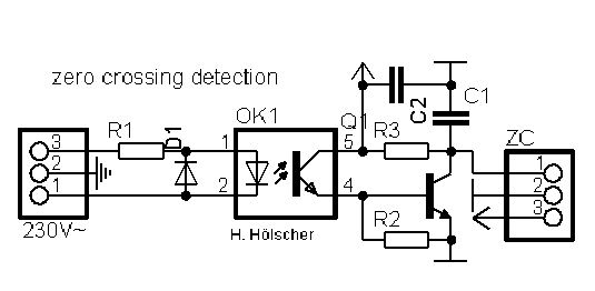
This zero crossing detection is needed for syncing a microcontroller with the mains. The more precise the circuit works, the better is the resolution of the dimmer pack. Because of this, I tested lots of such devices...
In my opinion, this simple circuit is one of the best:

parts:
| OK1 D1 R1A R1B R3 |
4N33 1N4007 27k / 1W 27k / 1W 10k |
The OK1-LED is powered via R1 in the positive part of the ac cycle. (D1 is for limiting the reverse voltage in the negative part.) If OK1 is conductive, it pulls ZC to GND otherwise ZC is pulled to VCC via R3. At the output, there should be a square wave with 50% duty-cycle. The edges indicate a zero crossing (but only the falling edges are used in the firmware).
The zc detection is part of the new power modules.
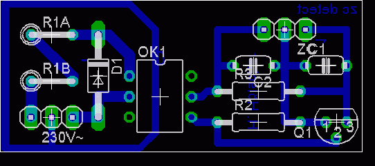
And here's the placement :

power units
With this dimmer modul you can dimm inductive loads up to 1kW or resistive loads up to 3kW per channel. (depends only on the used triacs)
The temperature must be between -20°C and +80°C.
The schematic is based on application notes of Teccor and was enhanced with information published by ON-Semiconductor.
schematic:

parts for the dimmer modul:
| OK1 T1 R1 R2 R3 R4 R5-S C1-D C2 OUT |
MOC3022 TIC 2XX 390Ω 360Ω 470Ω 39Ω / 0,5W not used 47nF / 630Vdc (MKS4 / RM7,5) 10nF / 630Vdc (MKS4 / RM7,5) 6.35mm Ribbon con. (Print, vert.) |
If the LED of OK1 is turned on, the optotriac discharges instantly C1-D into the gate of the main triac. A snubber network to limit inductive surges is made of C2 and R4. The optotriac is filtered by R3 and C1-D. The modul is powered via the common heat sink (similar to the switch). This way we can handle large currents without heavy wires. Of cause such a heat sink must not be directly connected to parts you can touch!!
I routed a combi pcb for the power modules of the dimmer and switch packs with 4 channels and an on-board zero crossing detection. Dimmer and switch modules use different parts.
pcb:
The board is 37mm x 111mm. The picture has a resolution of 300dpi.
placement:

To reduce EMI a toroidal choke (iron powder core) with 1-2mH for each channel is recommended.
temperature monitor
Switching large amounts of current, we have to make sure that the power modules won't get to hot. This is done with an NTC (6k8 @20°C) connected to A-In of the transceiver. For calibration move the poti R1 to the right stop and set the NTC to the shut down temperature. Now move R1 back until the red LED goes on and the pack shuts down.
switch mode
To use some channels in switch mode, you have to do the following steps:
1.) shut down the pack
2.) switch on DIP10 and the DIPs of the 'to be switched channels' (1-8).
3.) Start the pack again and wait 2sec.
4.) Choose the start address of the pack (DIP1-9) and switch DIP10 off.
60Hz mode
If your mains are 60Hz (USA), you have to jumper Spare1 to get the correct firing angles.
Debugging
To make the assembling of the dimmer easier, there is a wiring plan of the whole pack.
The change of a relevant channel is indicated by a flashing green LED. The red one repeats error codes until the bug is fixed:
| Pattern | Error | Solution | |
| flashing | There is no signal connected to the transceiver. | Connect the transceiver to the DMX bus. | |
| double flashing | The signal is not accepted as DMX. The transceiver cannot receive all required channels. |
Swap D+ and D- at the DMX connector. Transmit more channels or choose a lower start address. |
|
| fast flashing | The ZC-Detection is not connected to the transceiver. | Connect the ZCD or repair it. | |
| constant on | The power modules are too hot. | Wait until the temperature is OK again. Improve the heat sink. Build the temperature monitor and the A-In of the transceiver. |
|


